NOTICE: Many people ask if it is feasible to generate electricity with one of these hydroelectric turbines by installing it in a water system powered by an electric motor-driven pump. The answer is almost always NO. The reason usually is that the restriction caused by the turbine will make the pump work harder, consuming far more electricity than could possibly be generated by the turbine. Another common reason is that the turbine system cost is so much higher than the value of the small amount of electricity generated that the payback time period is many decades or longer. These hydroelectric systems are suited best for sites with naturally flowing streams that fall down a hillside.
We offer a variety of small hydroelectric generators, both AC and DC output. The DC generators are designed to be 12, 24 or 48 volt battery chargers, operating from a relatively small volume of water. They charge batteries 24 hours a day and the power can be drawn from the battery as needed, As little as 100 gallons per minute (GPM) falling 10 feet through a pipe, or 5 gallons per minute falling 200 feet through a pipe, can supply enough power to operate lighting and small appliances a small cabin or household. In areas where there is a long rainy season and a mountain stream that can be used, a small hydro system can work well with solar modules, both charging the same battery. When it is rainy and the solar modules are putting out less power, the hydroelectric system wilt be at its peak. Our small AC hydroelectric units use induction generators and are designed to operate isolated from the grid.
By contrast, larger typical AC power hydroelectric systems, designed to deliver ready-to-use 120/240 VAC power, are not practical for most people because they need a constant water supply large enough to supply the peak power output that will be required, usually a minimum of several thousand watts, requiring hundreds or even thousands of gallons per minute, depending upon the pressure available. Besides requiring large amounts of water, these turbines require large pipe diameters and expensive regulating systems that can maintain proper frequency and voltage at all times. If you believe you have a site suitable for a larger AC hydroelectric system like this, use the output calculator immediately below and then go to our Large Hydroelectric Generator page.
How much power can you generate?
The amount of power available depends on the dynamic head, the amount of water flow and the efficiency of the turbine/generator combination. To get an idea about available power in watts, multiply the head in feet, times flow in GPM, times 0.18 times efficiency. The combined efficiency of the turbine and generator ranges from 40% to 80%, with higher efficiency at higher heads and for larger generators. To get a rough idea, use 0.50 (representing 50%) as a multiplier for efficiency. Here are example computations using the minimum parameters mentioned above.
10 ft x 100 gpm x 0.18 x 0.50 eff = 90 watts
200 ft x 5 gpm x 0.18 x 0.50 eff = 90 watts
Or simply use the calculator below to estimate power and energy output using these formulas. Enter the pressure, flow and supply pipe length and press the "Calculate Output" button to display results.
Note, to run this calculator JavaScripts must be enabled on your browser.
For a graph of typical values using the above formula click the thumbnail image below:
A hydroelectric turbine operates from the pressure at the bottom end of a pipeline. This pressure, usually measured in pounds per square inch (PSI), is directly related to the head, or vertical distance from where the water goes into the pipe at the top of the pipeline, to the turbine located at the bottom of the pipeline. The pressure at the lowest point of a pipeline is equal to 0.433 times the vertical distance in feet, called head. Pressure is important because it is a determining factor in how much power is available and what type of pipe is required. Polyethylene pipe can be used for pressures up to 100 PSI, PVC pipe is available with pressure ratings from 160 to 350 PSI and steel pipe can withstand 1000 PSI or more. Check with your local plumbing supplier for pipe ratings.
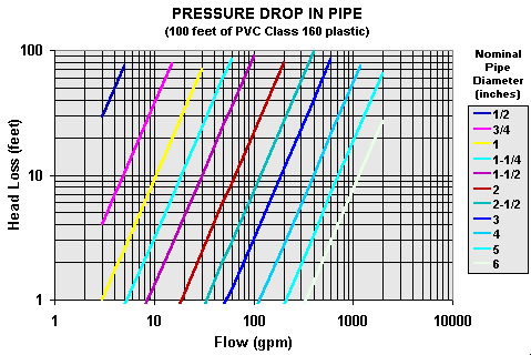
Pipe diameter is very important. All pipelines will cause the water flowing in them to lose some energy due to friction. The pipe must be large enough for the maximum quantity of water it will carry. The pressure at the bottom of a pipeline when water is not flowing is called static pressure. When water is flowing through the outlet or nozzle of the hydroelectric turbine, the pressure at the outlet is the dynamic pressure or running head. For an existing system, the maximum hydraulic power is available to the turbine when the dynamic pressure is approximately 2/3 of the static pressure. See graph below for pipe losses.

If you install a gate valve on the pipeline just above the turbine and a pressure gauge on a "T" fitting just above the gate valve, you will read the static pressure on the gauge when the valve is closed and the dynamic pressure when the valve is opened. The maximum power that can be delivered by a pipeline will occur when the dynamic pressure is approximately 2/3 of the static pressure. The actual flow rate of the water in a hydroelectric system is determined by the diameter of the nozzle. We will supply a turbine with the proper size nozzle for your site, depending on the head, flow, length and diameter of the pipe.
The power examples above can be adjusted for this pressure drop by subtracting it from the head. If 3 inch pipe is used for the 100 gpm example and 1 inch pipe is used in the 5 gpm example, and the pipes are 200 feet long, we have:
(10 ft - 3 ft x 2) x 100 gpm x 0.18 x 0.50 eff = 36 watts
(200 ft - 2.6 ft x 2) x 5 gpm x 0.18 x 0.50 eff = 88 watts
It is apparent from these examples that pipe losses can be significant in high flow rate designs.
We carry hydroelectric generators made by several companies. Use the descriptions in our online catalog to help determine which turbine will work better for your site and power requirements. We also offer larger turbines rated up to 1 MW and more.
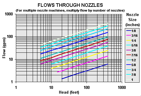
Power output of a hydroelectric generator is determined by the pressure of the water at the nozzle and the amount of water flowing out of the nozzle. The larger the nozzle, the greater the flow will be. The nozzle must also be sized small enough to keep your pipeline full and keep the speed of the water in the pipe below 5 feet per second.
The nozzle selection chart below shows water flow through various size nozzles at given pressures. Use this chart to determine what size nozzle and how many nozzles you need to accommodate the flow of water you have and to deliver the amount of power you need.

If you have good mechanical ability you can assemble your own small hydroelectric system. The runner is the most difficult part to make, but you can buy one from us, make your own housing and get a generator locally.
A pressure gauge in the pipe feeding your turbine, installed before the shutoff valve, can help you check proper operation and diagnose problems. When the valve is shut off the gauge will read the static pressure in pounds per square inch or psi (head in feet x 0.433). When the valve is turned on the gauge will read a lower pressure. The difference between these two pressures represents your loss due to friction in the pipe. The greater the flow, the greater your loss will be.
To determine the feasibility of your stream or pond for producing electricity you must estimate the head pressure (elevation drop) and available flow.
The Head measurement can be performed using several techniques. A garden hose can be routed from the upper end of the stream at the prospective intake location down to the lower elevation where you might locate the turbine. Allow the stream to fill the hose until water flows out of the lower end. Then raise the lower end until the water just stops spilling out of the hose. Measure the height between the end of the hose down to the planned location of the turbine. This measurement in feet is the static head. Or attach a pressure gauge to the end of the hose to measure the pressure directly. If the distance or height is too great to measure using a single section of hose, join several sections together. Or, make several intermediate measurements using this technique and add the heads together.
Alternative methods include use of a surveyor's transit, or a carpenter's level and measuring stick, an altimeter, or the gps on some smart phones.
Flow can be measured by channeling the water into a pipe using a temporary dam to fill a container of known volume. Divide the container volume in gallons by the time to fill in minutes to get gallons per minute (gpm).
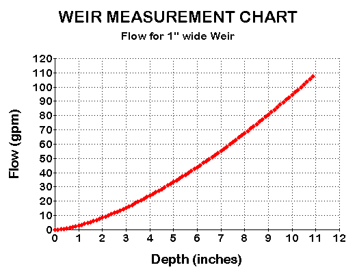
A more versatile method is to use a weir. Cut a rectangular opening in one edge of a board or piece of sheet metal. Then set this in the stream to act like a dam with the water flowing through the opening. Measure the depth of the water flowing through the rectangle and the width of the rectangle.

Note that because the surface of the stream as it approaches the weir may fall as the water accelerates toward the opening be sure to measure the depth at least 1-4 feet behind (up stream) of the weir. See diagram below.

Using this measurement go to the chart below and read the value in gpm of the flow through a 1" width of the rectangle. Multiply by the total width to get total flow.

Many states offer financial incentives for installing alternative energy systems. Some of these may apply to hydroelectric systems. Click here to review your state incentives.
Let us help you design the system
If you think you have a suitable site, email us and we will help you choose the best unit for your situation. Determine the following information about your site before you contact us:
1. Head - The total vertical elevation from the place where the water enters the pipe to the point where the turbine will be located.
2. Flow - The number of gallons per minute that are available.
3. Distance - The length of pipe that will be necessary to carry the water from the pickup to the turbine. If the pipe is already installed, what is the type and diameter?
4. Location - Distance from turbine to batteries.
State and Federal Resource Studies
There have been a number of federal and state studies done to assess the available potential sites for small hydroelectric generators.
| Click to View Information | Description |
 |
Low hear/low power water energy sites in the conterminous United States - Figure 12 from Water Energy Resources of the United States with Emphasis on Low Head/Low Power Resources (below) |
 Select a state to view the report. |
State Resource Assessment Reports
The resource assessment has been completed for 49 states (no report was generated for Delaware because of scarce resources). The completed work has identified 5,677 sites in the United States with undeveloped capacity of about 30,000 MW. You may view an individual state report by clicking on the United States map below. Some paper versions of these reports had photos which are not included in these online versions. The appendices are in text format and are described below. Appendix A summarizes the hydropower capacity for the state Appendix B lists the hydropower capacity alphabetically by River Basin, with the stream name/plant name arranged alphabetically under each river basin Appendix C lists these sites numerically by FERC number Appendix D provides a page on each site, listing all the environmental factors, KW capacity, location, owner's name, etc. and is organized by FERC number Please note that these reports describe sites that are generally of larger power potential the we sell. But these are valuable for determining what areas of each state will also have smaller sites. |
 Main Report |
Water Energy Resources of the United
States with Emphasis on Low Head/Low Power Resources - Idaho
National Engineering and Environmental Laboratory, 2004. Analytical assessments of the water energy resources in the 20 hydrologic regions of the United States were performed using state-of-the-art digital elevation models and geographic information system tools. The principal focus of the study was on low head (less than 30 ft)/low power (less than 1 MW) resources in each region. The assessments were made by estimating the power potential of all the stream segments in a region, which averaged 2 miles in length. These calculations were performed using hydrography and hydraulic heads that were obtained from the U.S. Geological Survey’s Elevation Derivatives for National Applications dataset and stream flow predictions from a regression equation or equations developed specifically for the region. Stream segments excluded from development and developed hydropower were accounted for to produce an estimate of total available power potential. The total available power potential was subdivided into high power (1 MW or more), high head (30 ft or more)/low power, and low head/low power total potentials. The low head/low power potential was further divided to obtain the fractions of this potential corresponding to the operating envelopes of three classes of hydropower technologies: conventional turbines, unconventional systems, and microhydro (less than 100 kW). Summing information for all the regions provided total power potential in various power classes for the entire United States. Distribution maps show the location and concentrations of the various classes of low power potential. No aspect of the feasibility of developing these potential resources was evaluated. Results for each of the 20 hydrologic regions are presented in Appendix A, and similar presentations for each of the 50 states are made in Appendix B. http://hydropower.inel.gov/resourceassessment/ |
 |
Virtual Hydropower Prospector This geographic information system (GIS) tool was designed to assist you in locating and assessing natural stream water energy resources in the United States. The first step in using this tool is to select one of the 20 hydrologic regions using the Region Selector. Each region selected will open a new map window for that region. VHP uses popup windows. It will not operate properly if window popup is disabled. Select the Popup Enabling button for instructions on how to enable window popup. VHP displays the locations of U.S. natural stream water energy resources and their gross power potential as determined by an analytical process. It also shows you the locations of feasible potential hydropower projects which have been determined using a set of feasibility criteria. For these potential projects, a more realistic power potential has been estimated using realistic development criteria. Context features such as cities, roads, power infrastructure, land use, etc. can be displayed to assist you in performing preliminary site assessments. VHP uses data sources not requiring a license for public display. A list of data sources is accessible by selecting the Data Sources button. The location of features and the associated attribute information are for indication only. Actual on-site locations, measurements, and evaluations must be undertaken to verify information presented by VHP and assess a site’s feasibility for development. |
This information was obtained primarily from the state of
Oregon web site at the link below. Some of it may not apply to small
micro hydroelectric projects in your state and regulations may be completely
different for regions outside the USA.
http://www.oregon.gov/ENERGY/RENEW/Hydro/Hydro_index.shtml
Access to water and the use, control and diversion of water flows is subject to federal and state regulation. Other regulations apply to any physical alteration of a stream channel or bank that may effect water quality or wildlife habitat. This is true regardless of whether or not the stream is on private property. If your project will have minimal physical impact, and you are not planning to sell power to a utility, there is a good chance that the legal process will not be too complex.
There are many local, state, and federal regulations that govern, or will effect, the construction and operation of a hydroelectric power plant. The larger the system, the more complicated, drawn out, and expensive the permitting and approval process will be. Penalties for not having the permits or necessary approvals can be severe. You will not escape the consequences by pleading ignorance. Although the legal process may seem burdensome, the intention of the laws is to protect all users of the resource, including the plant, fish, and animal communities that utilize the water.
When planning a hydroelectric system, your first point of contact should be the county engineer. He or she will be the most informed about what restrictions govern the development and/or control of water resources in your area.
The two primary federal agencies that you will need to deal with are the Federal Energy Regulatory Commission (FERC) and the U.S. Army Corps of Engineers. Try contacting the nearest office to you to see if they will assist you; both may be listed in the U.S. government section of your phone book.
FERC is responsible for licensing all non-federal government hydroelectric projects under its jurisdiction. A hydroelectric project is within the jurisdiction of FERC if any of the following conditions apply: the project is on a navigable waterway; the project will affect interstate commerce (i.e., if the system is to be connected to a regional electric transmission grid); the project uses federal land; or the project will use surplus water or waterpower from a federal dam. You will need to consult with FERC in order to determine whether or not your project falls under FERC’s jurisdiction. If it does, then you will need to apply for a license or exemption from FERC. The FERC application process will require contacting and consulting other federal, state and local government agencies, and providing evidence that you have done so.
If your project involves a discharge of dredge or fill material into a watercourse or wetland, you may also need a permit from the Army Corps of Engineers. Your local district office of the Corps should help determine if you will need a permit.
* US Army Corp of Engineers (engineer manuals)
You will also need to determine whether, and to what extent, you can divert water from the stream channel, and what restrictions apply to construction and operation of the system.
In Oregon, the Water Resources Department regulates water rights. You may need a separate water right to produce power, even if you already have a water right for any other use. You should consult with the state Department of Fish and Wildlife in determining the ultimate design and operation of your system.
Other federal government agencies that may require permits include: the U.S. Fish and Wildlife Service; the Federal Aviation Administration (if a power line will be constructed near an airport); and the U.S. Forest Service or Bureau of Land Management, if the project will use land administered by these agencies.
Note that Micro hydroelectric generators are not currently UL Listed. If your installation will be inspected make sure this is acceptable before ordering.
